Overview
This study from the group of Cheolmin Park in the Department of Materials Science and Engineering at Yonsei University, co-authored by Jungmok Seo (then at the Department of Electrical and Electronic Engineering, Yonsei University), who now leads the BLISS Lab at Yonsei University, built solution-processed alternating current electroluminescent (AC EL) devices in blue (B), green (G) and red (R). The emitting layers combined fluorescent polymers, multiwalled carbon nanotubes (MWNTs) and block copolymer micelles, and the abstract reports brightness of approximately 2300, 6000 and 5000 cd m⁻² for blue, green and red emission.
Background
AC EL devices can be made from solution-processed and printable emitters, but the brightness of solution-processed AC EL devices had remained at a few hundred cd m⁻², and most work had addressed red, green and white emission. The authors proposed that markedly improving blue, green and red brightness was one way to increase the market availability of AC EL devices.
Design and approach
Each device stacks four layers: an indium tin oxide (ITO) bottom electrode, an insulator, a solution-processed emitting layer about 500 nm thick and a top electrode. The emitting layer blends a fluorescent polymer with MWNTs for carrier injection and poly(styrene-block-4-vinylpyridine) (PS-b-P4VP) micelles, whose polystyrene coronas wrap the nanotubes for dispersion while excess micelles dilute the polymer chains and suppress interchain nonradiative quenching; the optimized composite used a polymer to micelle ratio of 4 to 1 with approximately 2 wt % MWNTs. Green and red emission were further increased by fluorescence resonance energy transfer (FRET) in blends of blue, green and red polymers.
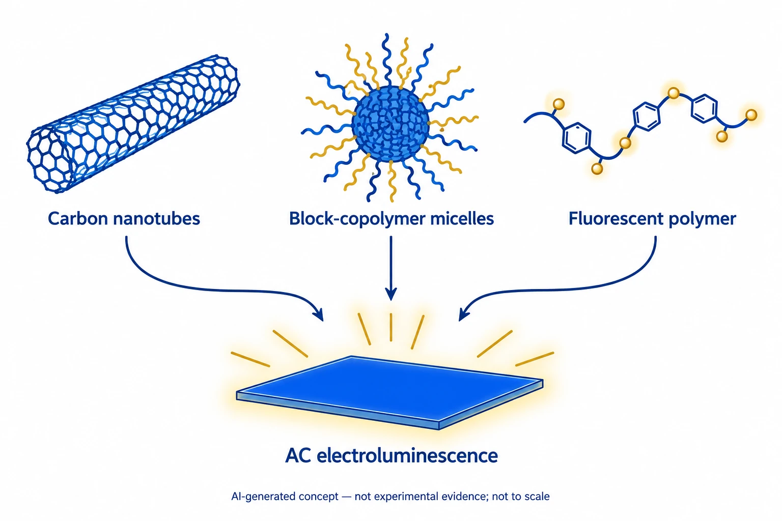
This AI-generated, not-to-scale concept diagram connects carbon nanotubes, block-copolymer micelles and fluorescent polymers with AC light emission. The material and light symbols do not reproduce molecular structures, an actual device or experimental results.
Generated for this library to illustrate the design; it is not a figure from the paper and does not show measured data.
How it was evaluated
Luminance-voltage characteristics, EL spectra and Commission Internationale de l'Eclairage (CIE) coordinates were measured mainly at 400 kHz for single-polymer devices, binary B-G, B-R and G-R blends and a ternary B-G-R blend on 200 nm SiO2 insulators. Time-resolved emission, luminous power efficiency and current efficiency were measured under square-pulse or sinusoidal inputs, and the devices were also built with a high-k Al2O3 insulator, with hand-written Ag paste electrodes, on flexible poly(ethylene terephthalate) (PET) and with epoxy encapsulation for operation over time.
Key results
Single-polymer devices with MWNTs reached maximum brightness of 2380 cd m⁻² (blue, ±80 V), 950 cd m⁻² (green, ±60 V) and 1150 cd m⁻² (red, ±60 V) at 400 kHz, with EL peaks at 480, 530 and 650 nm; the abstract and conclusions give the blue brightness as approximately 2300 cd m⁻². Emission was very weak without nanotubes and increased with MWNT content up to approximately 2 wt %. Adding micelles increased brightness but also raised the operating voltage. Under ±110 V square pulses at 50 Hz, light was emitted at both polarities, and above 50 kHz the emission became constant and independent of frequency.
FRET raised green emission to approximately 6000 cd m⁻² in a blue-green blend (8:2). A ternary blend with weight fractions of 0.5, 0.25 and 0.25 for B, G and R emitted red light of approximately 3100 cd m⁻², with peaks at approximately 480, 530 and 640 nm for the B, B-G and B-G-R devices and CIE coordinates of (0.625, 0.373), (0.385, 0.577) and (0.156, 0.221) for red, green and blue emission. The EL spectra did not change with increasing voltage.
Luminous power efficiency was 0.05 to 0.15 lm W⁻¹ for all three colours under ±50 V sinusoidal input at 50 kHz, and the current efficiency of a green device was approximately 0.6 cd A⁻¹ at 1000 cd m⁻². The authors noted that vacuum-processed AC EL devices with 9 stacked layers had reached 0.37 lm W⁻¹ and 2.7 lm W⁻¹ at 2 kHz. Under DC bias, the current was approximately 10⁻⁶ A and no light was emitted. Replacing SiO2 (k∼3.9) with Al2O3 (k∼9) increased the red brightness of the B-G-R device to approximately 5000 cd m⁻², and 16 cells of 2 × 2 mm² were operated together.
Light was also emitted beneath hand-written Ag paste electrodes. On flexible PET, the brightness fell to approximately 500 cd m⁻² because of substrate nonuniformity, which caused local breakdown at high AC voltage, and the device operated at a bending radius of approximately 15 mm. With epoxy encapsulation, brightness decreased from approximately 100 to 50 cd m⁻² after 7 h, while an initial brightness of approximately 30 cd m⁻² at a slightly lower voltage did not change over long operation; the abstract and conclusions state operation for over 15 h.
Open questions
The authors described the power efficiency as slightly low compared with vacuum-processed AC EL devices with more elaborately stacked layers and stated that more systematic investigation was underway to improve it. The flexible device on PET showed lower brightness and local breakdown at high voltage due to substrate nonuniformity.
Related research
AC Field-Induced Polymer Electroluminescence with Single Wall Carbon Nanotubes
The related paper’s abstract describes AC charge injection assisted by single-walled carbon nanotubes. This study combines multiwalled nanotubes, micelles and energy transfer between different-colour polymers.
Abstract-based introductionSources used in this summary
This summary is based on the publisher PDF of the article, including the Methods, Table 1 and figure legends; the Supporting Information was not reviewed, and values given only in Table 1, some of which differ from the corresponding values in the text, were not used.